For the past few months, I have been working on hobby projects like building drones and robotic arms, but it’s a good idea to start from scratch if we’re serious about this path.
We will use the Arduino Uno, an open-source microcontroller board, to create an embedded system that blinks a light. But what do those words even mean?
Let’s start with microcontrollers. As the name suggests, it’s a small (micro) device that controls (controller) some parts of a system, like sensors, motors, or LEDs. A microcontroller has a CPU (central processing unit) to make calculations, memory to store its program, and peripherals to interact with the world.
So, what is an embedded system? It’s a mix of hardware and software that has a specific task to perform. All embedded systems have a computer within a larger system — that’s why it’s called “embedded.” With this definition, any electronic system with computing power (except for general-purpose computers) is an embedded system! If it were up to me, I would’ve never coined the phrase embedded — I’d just call it mixware (software + hardware).
Now that we know about microcontrollers and embedded systems, let’s blink that light. We’ll use Arduino, an open-source platform that lowers the barrier for people like me to enter electronics. We’ll use the Arduino Uno board (it has a microcontroller called ATmega328P) and the Arduino IDE to write and upload our code.
When you open the Arduino IDE, you will see board and port selections. Board is your hardware — you select it so that the Arduino IDE compiles the code for that microcontroller. Port is the connection used to upload the code.
Arduino IDE has nice example code. Let’s go to File → Examples → 01.Basics → Blink.
You will see a file called Blink.ino. You save your “sketch” (Arduino program) as an .ino file. It’s basically a less scary version of C++ code. You only create setup() and loop() functions, and it’s ready to go.
The following code blinks the built-in LED on the Arduino at 1-second intervals:
void setup() {
  pinMode(LED_BUILTIN, OUTPUT);
}

void loop() {
  digitalWrite(LED_BUILTIN, HIGH);
  delay(1000);
  digitalWrite(LED_BUILTIN, LOW);
  delay(1000);
}
The setup() function only runs once when the board is powered on or the reset button is pressed. Then, it runs the loop() function forever.
pinMode() tells Arduino how you want to use a specific pin — like making it an input (to read data) or an output (to send signals, like turning on an LED).
Pins are the connection points on the Arduino board. To see which pins the Arduino has, you can check its pinout on the official website.

pinMode(LED_BUILTIN, OUTPUT); → This means we are telling the Arduino Uno to use the built-in pin as an output. LED_BUILTIN is a constant for the pin number that controls the onboard LED on the Arduino board. It’s useful because different Arduino boards might have different built-in LED pins, and with this constant, Arduino automatically converts it to the correct pin for each board.
digitalWrite(LED_BUILTIN, HIGH); → This function writes HIGH to a digital pin. Arduino sends voltage (5 volts on Uno) to the LED, and it lights up.
delay(1000); → We wait for a second. (Microcontrollers can “keep time” because they have a built-in clock inside that ticks millions of times per second.)
digitalWrite(LED_BUILTIN, LOW); → Arduino stops sending voltage to the built-in LED. It stops glowing.
delay(1000); → We wait for a second again.
And this loop runs forever as long as we provide power to the board.
But there’s a new notion here: digital pin? Well, it’s digital because it can only have two states: HIGH and LOW. You might guess that this functionality can be used for “trigger”-type events like pressing a button or controlling an LED. There are also really interesting concepts like PWM that we’ll learn later.
On analog pins, you can read continuous values. And instead of giving HIGH or LOW, you give a range of voltage (0–5V, for example), and Arduino converts this voltage to a new range (0–1023) using an ADC (analog-to-digital converter).
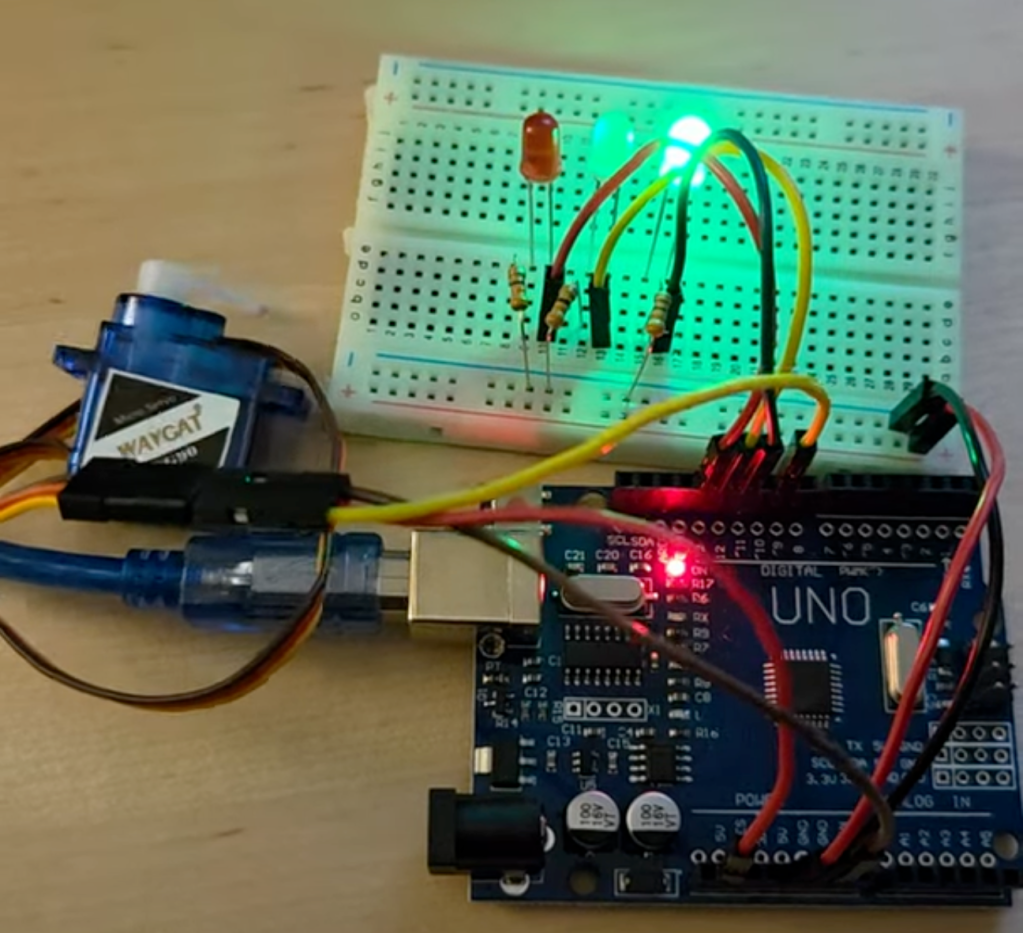
Blink was a great start. But what if we want to plug external components into the Arduino? I want to create a traffic light with 3 LEDs. I also want to connect a servo and change its position based on the lights.
For that, we need LEDs, resistors, a servo motor, jumper wires, and a breadboard. It would be much easier if we could just plug the LEDs and motor directly into the Arduino without using a breadboard, but we simply don’t have enough pins on the Arduino to connect all the components. So, let’s start!
Before we start wiring, it helps to understand what’s going on inside the Arduino Uno — especially how it talks to your computer and runs your code.
If you look at the schematic (a symbolic map of the circuit), you’ll notice that the Arduino Uno revolves around two important microcontrollers:

ATmega328P – the main processor (the brain), which runs our code
ATmega16U2 – acts as a USB-to-serial converter
You can see that the bottom-left portion of the schematic is entirely focused on the USB circuitry and the ATmega16U2 — this part handles the communication between your PC (USB) and the ATmega328P (serial).
Now we’ll extend this circuit with our new components. Let’s grab our breadboard. It looks like this:

Once you see the inside it becomes easier to understand breadboards:

As you can see, it’s just metal strips to conduct electricity. We’re basically playing a game of creating a closed loop with wires and electrical components.
Below, you can find a circuit that connects LEDs to an Arduino with resistors. I had 330-ohm resistors, so it will be slightly dimmer, but we could’ve used even 150Ω resistors without damaging the LEDs.

You can check out how to read resistor color codes on the website below.

Now that we’re getting into code, it’s a good time to introduce a couple of new concepts: variables and functions.
const int GREEN_PIN = 11;
const int GREEN_PIN_DELAY = 2000;

void blinkLED(int pin, int delayTime) {
  digitalWrite(pin, HIGH);
  delay(delayTime);
  digitalWrite(pin, LOW);
}
We will do this for all three lights, and result looks like this:
When we want to add a servo, we’re dealing with a much more complex component than an LED. Thankfully, we have libraries for this. A library is code written by someone else — we can simply drop it into our project.
We’ll use the Servo library. With it, we can create a servo object and use its functions, like attach() and write().
The final code looks like this:
#include <Servo.h>  // Include Servo library

const int RED_PIN = 13;
const int YELLOW_PIN = 12;
const int GREEN_PIN = 11;
const int SERVO_PIN = 9;

const int RED_PIN_DELAY = 2000;
const int YELLOW_PIN_DELAY = 1000;
const int GREEN_PIN_DELAY = 2000;

Servo myServo;  // Create a servo object

void setup() {
  pinMode(RED_PIN, OUTPUT);
  pinMode(YELLOW_PIN, OUTPUT);
  pinMode(GREEN_PIN, OUTPUT);
  myServo.attach(SERVO_PIN);   // Connect servo to pin 9
  myServo.write(0);            // Start in closed position
}

void blinkLED(int pin, int delayTime, bool activateServo = false) {

  digitalWrite(pin, HIGH);
  if (activateServo) {
    myServo.write(180);
  }

  delay(delayTime);
  digitalWrite(pin, LOW);

  if (activateServo) {
    myServo.write(0);
  }

}

void loop() {

  blinkLED(RED_PIN, RED_PIN_DELAY);
  blinkLED(YELLOW_PIN, YELLOW_PIN_DELAY);
  blinkLED(GREEN_PIN, GREEN_PIN_DELAY, true);  // Only green triggers servo

}
It looks a bit messy, but here’s the final result:
That’s all for today. If you’re into robotics, AI, or just like watching someone mess around with hardware, stick around. Let’s build some physical intelligence!

Yorum bırakın