Schematics might look intimidating at first, but they’re really just guides. In this post, I’ll walk through the basics of schematics, pinouts, and datasheets — using a really simple board to keep things clear.
Arduino Pro Mini
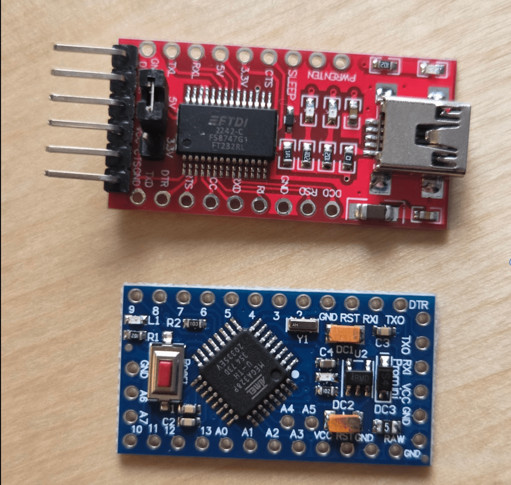
We will use the Arduino Pro Mini because it’s a simple board, making it a good choice for exploring schematics, pinouts, and datasheets along the way. Remember the ATmega328P microcontroller? Yes, it uses the same microcontroller as Arduino uno. It looks like this:

Pinout diagrams show the purpose of each pin, so you know exactly where to plug things in. Pins might seem straightforward at first — but take a look at the Pro Mini’s pinout diagram:

In the upper-left legend, you’ll see what the color codes mean:
⚪️ White (Name): These are the human-readable pin names printed on the board, like D3, A0, or RESET.
🟢 Green (Arduino): These are the names you can use in Arduino code. For example, you can write digitalWrite(D3, HIGH) — but you can also just use the pin number: digitalWrite(3, HIGH).
🔵 Blue (Port): These are internal port names like PB3 or PD2, used in lower-level programming. We’ll come back to these in the next blog post when we get into bare-metal programming.
FTDI module
You may have noticed the FTDI Header at the top of the board. This is where you connect an FTDI module — a USB-to-Serial converter. Since the Arduino Pro Mini doesn’t have a built-in USB port, you’ll need this module to upload code from your computer to the board.

We didnt need an FTDI adapter in the Arduino Uno because it has a built-in usb-to-serial chip. Remember the huge blob of complexity in the Arduino Uno’s schematics? Now it’s FTDI’s job to handle the conversation.
Speaking of schematics, Pro Mini’s diagram looks like this:

This time, we can dig a little deeper than in the first blog post and explore some of the more interesting parts of it.
Schematics
- Voltage regulator

On the top left, you can see how the Pro Mini takes a raw input voltage (5V–16V) and converts it into a regulated 3.3V or 5V using the MIC5205, a voltage regulator. (My board uses 5V.)
- Reset

This part is the reset circuit — it allows you to restart the microcontroller either automatically or manually. It uses a few components: a resistor (R2), a capacitor (C2), and a button (S1).

- AREF

The Analog Reference (AREF) pin helps measure smaller voltages more accurately by setting the maximum voltage that analogRead() uses for comparison.
Normally, analogRead() measures voltages between 0 and 5 volts (on 5V boards) and converts that range into values between 0 and 1023.
For example, if it measures 2.5V, it returns:
analogRead() = 1024 × (2.5 / 5) = 512
However, the Arduino doesn’t always receive a perfect 5V. If it’s powered through a USB port, it might only get around 4.8V — which introduces a small error in the measurement.
One way to fix this is to provide a stable, lower reference voltage — like 3.3V — through the AREF pin. This lets you measure voltages in the 0–3.3V range more precisely, using the full 0–1023 resolution.
- External crystal oscillator

Remember the clock inside the microcontroller from the previous blog?
Turns out, you can also add a crystal oscillator externally for more accurate timing. The ATmega328P has an internal 8MHz oscillator, but with this external module, we can get better accuracy and higher speed — up to 16MHz.
By the way, if you’re wondering what this external crystal oscillator looks like — it’s this little guy:

- I²C (Inter-Integrated Circuit) communication

I2C is a communication protocol that lets multiple devices talk to a microcontroller using only two wires: SDA and SCL (27 and 28 in schematics).
SDA stands for Serial Data: it’s the line where the actual data is transmitted.
SCL stands for Serial Clock: it keeps all the data transfers in sync between devices.
If you look at the dotted rectangle, you’ll see resistors R1 and R3. These resistors are not physically on the board — the box is just a suggestion that you can add them if needed. They’re called pull-up resistors, because they “pull” the SDA and SCL lines up to the high voltage level (VCC) when no device is actively sending data. This keeps the signal stable and prevents it from “floating” or picking up noise.
If you look back at the reset circuit, you’ll also notice a pull-up resistor used there. I wanted to point it out here because the I2C setup is a bit easier to understand — so it might help make sense of what’s going on in both places.
- FTDI connection

We can follow this diagram to connect the FTDI adapter to our board.
JP1 represents the FTDI adapter. Once it’s connected, your computer can communicate with the board just like it would with a regular Arduino that has a built-in USB port.
That’s it for this post!
We went through the Pro Mini’s schematic, looked at how power regulation works, explored the microcontroller, talked about reset and I2C circuits, and saw how to connect an FTDI adapter. It might seem like a lot at first, but once you start recognizing these patterns, schematics become way less intimidating.
In the next post, we’ll go a bit deeper: looking at internal ports, bare-metal programming, and what’s actually happening when you write to a pin. Stay tuned!

Yorum bırakın