I had a nice little egg cooker… until I broke its button. You might be surprised how important that button was. I tried all sorts of caveman tactics to turn the thing on. Nothing worked. Apparently, that small plastic button was the gatekeeper to my breakfast. And I told myself, “If I have a 3D printer, why don’t I just make the button?”
Now, I’d played around with Blender before—I even 3D-modeled some game characters and objects. At one point, I measured the iconic tower at my university and created a miniature 3D model of it. I 3D printed a few, thinking I could eventually sell them to visiting high school students as souvenirs. So naturally, I thought I knew 3D modeling. But when I tried to design a functional replacement button for my egg cooker, I quickly realized I was stepping into a completely different world: CAD (Computer Aided Design)
Blender is fantastic for visual art and creativity. It’s flexible, freeform, and great for sculpting game assets or animated characters. CAD modeling, on the other hand, is built for real-world engineering. It’s about exact measurements, constraints, and making sure that your design doesn’t just look good—it fits and functions perfectly in the physical world. That’s why I decided to use Fusion 360 for this project.
Before even opening the computer, the first step is to measure. One important thing to keep in mind: only measure what actually matters for the function. Our button looked like this before it broke:

For me, the minimum measurements needed to create a working button were something like this sketch:

Speaking of sketches, Fusion 360 starts every design with a sketch. You choose a plane, draw 2D shapes like circles, rectangles, or custom lines, and then use tools like dimensions and constraints to lock things into place. Once your sketch is ready, you can extrude it into a 3D object. Compared to freeform modeling, this workflow felt structured and surprisingly satisfying (Sorry Blender, but I don’t think I’m coming back)

You’ll typically use two main types in a sketch: solid lines, which define actual geometry that becomes part of the 3D model (like the circles that get extruded), and dashed lines, known as construction lines, which act as guides and won’t appear in the final model. In the sketch above, the dashed horizontal line is a construction line used to precisely place the flat edge of the D-shaped hole. With an incredibly simple object like this, all I had to do was select the faces and extrude! Here’s the final model:

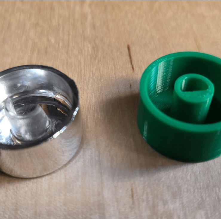
And finally—here’s the finished button in action.


On the left, you can see the original broken button and my 3D-printed replacement side by side. It fits, it turns, and the cooker is back in service. I also checked whether that area gets hot during use—and luckily, it stays cool enough for a PLA replacement to work just fine.
This post wasn’t meant to be a full-on CAD tutorial. Instead, I wanted to show what the design process actually looks like—from identifying the need, taking measurements, sketching in Fusion 360, modeling with intent, and finally holding a functional, real-world object you made from scratch. It’s a small fix. But being able to design and print a custom solution like this feels amazing.

Yorum bırakın